• Formation hydraulique : Explication simple, comprise de tous. Support sur clef USBFormation hydraulique :...

    50,00€ inc. tax 47,39€ excl. tax

    Details
  • Promotion

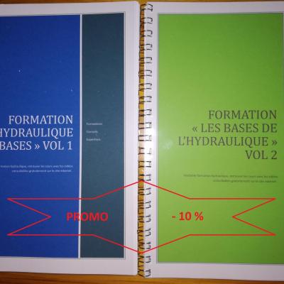
    3 livres pour se former en hydraulique. 55 cours associés à des vidéos consultables...

    150,00€ 135,00€ inc. tax
    142,18€  127,96€ excl. tax

    Details
  • Promotion

    620,00€ 496,00€ inc. tax
    516,67€  413,33€ excl. tax

    Details
  • Promo

    55,00€ 49,50€ inc. tax
    52,13€  46,92€ excl. tax

    Details

Disassembly and operation

of external gear pumps

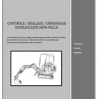
  • La procédure de contrôle, réglage et dépannage est décrite à l'aide d'un schéma de mini-pelle 1.6T....

    50,00€ inc. tax 47,39€ excl. tax

1- Role

The role of the external gear pump is to generate a flow.

It transforms the mechanical energy of the thermal or electric engine into hydraulic energy.

The gear pump is used on many installations. It withstands pressures up to 250 bars.

In view of its design, the gear pump is only fixed displacement.

At a moderate cost it is not repairable.

  Symbol:


Symbole pompe cylindree fixe 1

The drive shaft (2) rotates clockwise and drives the driven shaft (3) anti-clockwise. The effect of disengagement of teeth (A side) creates an increase in volume and causes a suction effect. The oil engulfs in the hollow of the teeth and is transported by the outside of the gears (cavities C). The meshing effect (R side) creates a reduction in volume and drives the oil back.

The pump housing (1), often made of aluminium, receives the suction and discharge ports.

 
Pompe a engrenage externe 3 1
  • Promotion

    Formation hydraulique de base niveau 1 complète en vidéo webcam enregistrée sur...

    120,00€ 120,00€ inc. tax
    113,74€  113,74€ excl. tax

    Details

The pump has no bearing, the gears rotate on plain bearings called binoculars.

  • 50,00€ inc. tax 47,39€ excl. tax

    Details
Pompe a engrenage externe 2 1
  • 50,00€ inc. tax 47,39€ excl. tax

    Details

A seal on each side of the binoculars ensures a hydrostatic balance. (Photo above)

This seal is located :

- On the lids as in the photo.

- Or on the binoculars.

- On a piece inserted between the binoculars and the lid.

  • Hydraulic hotline

    Résoudre vos problèmes hydrauliques rapidement HOTLINE (Réponse rapide) Résoudre...

    1 320,00€ inc. tax 1 100,00€ excl. tax

    Details
Pompe a engrenage externe 1 1
  • 50,00€ inc. tax 47,39€ excl. tax

    Details

Two O-rings between the pump housing and the covers provide external sealing.

  • Expertise: contrôle et réglage des pompes hydrauliquesExpertise pompe La pompe est un élément...

    0,00€ inc. tax 0,00€ excl. tax

    Details
Pompe a engrenage externe 4 1
  • Promo

    55,00€ 49,50€ inc. tax
    52,13€  46,92€ excl. tax

    Details

The shaft seal is in most cases drained to the suction port. The direction of rotation must be strictly observed, otherwise it will leak from the first seconds of operation.

It is possible to change the direction of rotation of the pump by inverting the binoculars.

Note : The suction port is always larger than the discharge port. (Except for very low flow pumps).

3- The choice

Gear pumps are cheap, maintenance is easy since they are not repairable.

They are not very sensitive to pollution and resist pressures up to 250 bars. (Not continuous).

They have a small footprint and are lighter than other types of pumps.

The noise and pollution that are created by the friction of the gables in the crankcase are the main disadvantages.

4- failures

The efficiency of a new gear pump is 85%. (Varies depending on the builders). From a yield of 70% it is advisable to change it because it reaches the end of life.

To test it, it is necessary to compare with a flowmeter the theoretical flow (or measured without any pressure) at the actual flow measured pump in load (maximum pressure of the circuit).

A leak at the shaft seal is often due to too much pressure in the crankcase caused by heavy wear on the pump. The pump needs to be replaced, changing the shaft seal is useless.

5- Some technical advice

Outside the drive torque, no radial or axial force should be applied to the pump shaft. (Except pump with counter bearing).

The suction line must be designed to achieve a maximum fluid circulation velocity of 2.5 m / s. (Reduce if possible, especially for large flows).

Here are some indications of flows according to dimensions of the pipes:

1 / 4 "   8 x 13 = 8 l / min

3 / 8 "   12 x 17 = 17 l / min

1 / 2 "   15 x 21 = 27 l / min

3 / 4 "   21 x 27 = 52 l/ min

1 "   26 x 34 = 80 l / min

1 "   1 / 4 33 x 42 = 130 l / min

1 "   1 / 2 40 x 49 = 190 l / min

2 "   50 x 60 = 295 l / min

2 "   1 / 2 66 x 76 = 513 l / min

3 "   80 x 90 = 750 l / min

The suction line must be as straight as possible. Avoid elbows and connections.

The suction line must be as short as possible. (Less than 1.50 m).

The height between the suction port and the oil level must not exceed 0.75 m.

It is advisable to place the pump under load, that is to say: the tank above the pump...

Do not use flexible materials to make the piping, vacuum and temperature tending to bring the walls closer and reduce the area of ??passage.

Ensure that the connections are properly tightened to prevent air intake.

The temperature of the oil in the tank must not exceed 60 ° C maximum.

The tank must take into account the quantity of oil that can be taken to ensure the different cycles in order to avoid the planing of the pump.

The tank must allow the fluid to settle any emulsions.

All piping returning to the tank must be return plunging.

The tank must be perfectly clean and impervious to external impurities.

It must be simple, either rectangular or cylindrical.

The hydraulic system must be equipped with an efficient filtration system.

  • Promo

    525,00€ 367,50€ inc. tax
    497,63€  348,34€ excl. tax

    Details
  • Promo

    525,00€ 367,50€ inc. tax
    497,63€  348,34€ excl. tax

    Details

  • 55,00€ inc. tax 52,13€ excl. tax

    Details
 

Add a comment

Anti-spam