2-Pressure calculation
2-1 Piston surface
S = π*R²
S : Surface in cm².
R : Piston radius in cm (16/2=8cm).
S = π *8²
S= 200,96 cm².
2-2 Pressure required
P = F/S
P : Pressure in bar.
F : Force in daN or Kg.
S : Piston surface in cm².
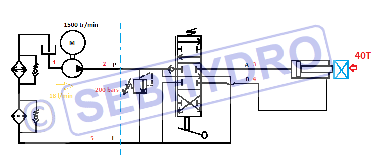
P = 40000/200.96
P = 199 bars : rounded to 200 bars.
We will take an external gear pump installed under load. (Tank above the pump).
3- Flow Calculation
3-1 Cylinder speed
The length of the cylinder 30 cm or 0.3 m must be exit in 20 seconds.
Is : 0.3/20 = 0.015 m/s
3-2 Flow required
Q = 6*S*V
Q : Flow in l/min.
S : Piston section in cm².
V : Cylinder speed in m / s.
Q = 6*200.96*0.015
Q = 18.08 l/min rounded to 18 l/min.
4- Calculation Displacement of the pump
The electric motor runs at a speed of 1500 rpm.
Q = q*N/1000
Q : Flow in l/min.
q : Capacity of the pump in cm3 / revolution.
N : Rotation speed in rpm.
18 = q * 1500/1000
18 = q* 1.5
q = 18/1.5
q = 12 cm3/t.
5- Directional valve size
The maximum flow rate through the directional valve is the pump flow multiplied by the cylinder section ratio.
Section Ratio: The difference between the piston surface and the annular surface.
Q = 18 *2 = 36 l/min.
We will choose a monoblock directional valve type 6/3 open center can pass 40l / min. The pressure relief valve is integrated in the directional valve.
6- Tank size
In industry, the size of the tank is 4 to 5 times the flow of the pump.
In on-board circuits (public works- agriculture) the size of the tank is between 0.8 to 2 times the flow of the pump.
More precisely, the tank must contain the useful volume (volume of the cylinders + pipes) + the tidal volume (return volume of the cylinders + volume of the accumulators) + the volume of sky (15% of the useful volume + tidal range).
We will take a tank of 35 l.
7- Power of the electric motor
P = p * Q / 540
P : Power in KW.
p : Pressure in bar.
Q : Flow in l / min.
P = 200 * 18 / 540
P = 6.66 KW we will take a standard engine 7.5 KW.
8- Power of the exchanger
If the installation only works for a few minutes a day, it is not necessary to install an oil cooler.
Otherwise, it is advisable to take an exchanger that can dissipate 35% of the installed power.
6.66 * 35/100 = 2.33 KW.
9-Pipe dimension
The dimensioning of the inside diameter of the pipes is done thanks to the chart below.

